Advanced landing pad
Key Considerations
The greater the separation between the ARC secondary units on the landing pad constellation the more accurate the ARC primary unit can measure the drone location left/right and forward/backwards, see Figure 15. This leads to lower variance measurements, meaning that the drone can hold at its intended position with greater accuracy and stability.
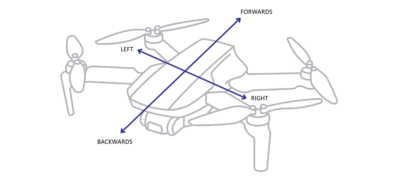
The pad size dimension has a square relationship with drone stability. A doubling of the pad size; for example, from 1.5m to 3m, would lead to 4 times better measurement accuracy and stability control left/right and forwards/backwards. If a typical pad size dimension is 2m x 2m, reconfiguring it to 1.4m x 1.4m would mean the drones ability to control and maintain a position in the air would be half as accurate (1.42≈2)
In addition, the left/right and forwards/backwards drone control accuracy is dependent on the drone’s height above the pad. This relationship is linear. For example, if the drone is 20m above the pad, then drone left/right and forwards/backwards control will be twice as stable as when the drone is 40m above the pad.
A further consideration is that the ARC Primary and Secondary have the same antenna field of view (FoV). This is nominally ± 45 degrees, however, when the aircraft is close to pad, FoV does increase. The shorter range ensures that Primary and Secondary can still communicate further off the central axis (also known as boresight).
At some minimum height of <1m above the ground pad the ARC system connection will be lost. In practice this shouldn't matter; the aircraft is at the point of landing and the best course of action at this point is to complete the landing. Any rapid adjustments of drone control at <1m altitude, as a result of deck pitch or roll due to a wave for example, are not desirable and likely to be unsafe.
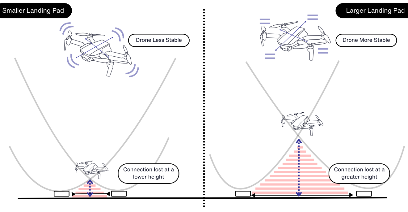
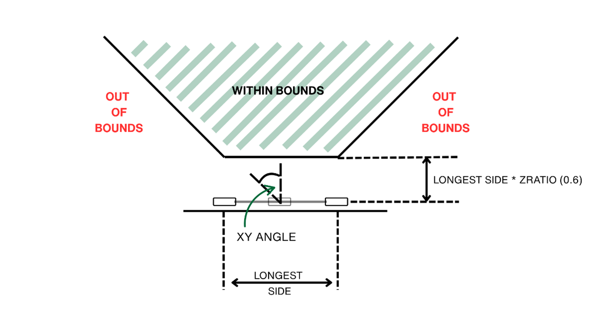
It is important to bear in mind that landing pad size does affect this minimum height. For a pad size of 2m x 2m, the height above the pad where the ARC system connection is configured to drop is 1.2m (calculated in the radar firmware at 0.6 x longest pad size, 2m in this example). A smaller pad, say 1.4 x 1.4m will reduce this height to 0.84m, but the drone is less stable in flight. Please note that the multiplier 0.6 is configurable if a user wants to pick a particular height. Further detail in Configure Out of Bounds (XYAngle and ZRatio).
It is important that the ArduPilot flight controller configuration DO_FAST_LANDING is configured TRUE. This must be configured to ensure continuous uninterrupted movement towards the deck, ensuring that the drone does not unnecessarily pause when a few metres above the pad, see Configuring ArduPilot for Precision Landing / Tethering for further details. DO_FAST_LANDING is supported from ArduPilot (ArduCopter) version 4.5.0 and onwards. Descent speed during landing manoeuvres towards the deck is typically set at 0.5 metres and has been tested at 0.8 metres per second. This can be set using the LAND_SPEED parameter.
Figure 16 illustrates the payoff between increasing and decreasing the landing pad size.
Secondary Unit Common Alignment and Centring
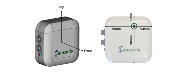
The landing pad requires three ARC Secondary units to be arranged in a triangular formation. All devices should be orientated in the same direction with the Front face of the device pointing vertically, see Figure 17. The measurement reference point when setting out ARC secondary units on a landing pad are also shown in Figure 17. When measuring distances between ARC secondaries for landing points, it is important that measurements are taken from this point. Figure 18 in the next section Landing / Tethering Position provides further detail on the landing frame axis.
Landing / Tethering Position
It is important to understand the axis of the landing pad and the landing point, or origin, which is the point for the land/tether position of the UAV. From the landing point the landing pad axes have positive Y-axis as forward, and the positive X-axis as left as shown in Figure 1818. Figure 18 and Figure 19, demonstrate two different positions the landing point could be configured in and how it determines the coordinates to each secondary from itself (0, 0). The projected secondary coordinates provide the basis for the trilateration configuration.
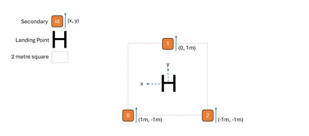
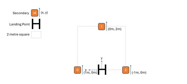
A trilateration binding is configured to set the landing point origin (Landing/Tether Point location) in relation to the statically mounted secondary devices.
View current configuration
See also Appendix H – Using the CLI,Appendix H – Using the CLI for a full description of the connection
procedure. Note that in earlier firmware versions the CLI did not support backspace during text entry.
From this version 5.3 onwards backspace is now supported.
Step 1: Show the current binding (as would be seen in Figure 18)
ARC_Primary:/>bndshow
coordinate systems available:
NATIVE
CARTESIAN
strategies available:
DRCT:
Update Configuration
Step 1: Clear bindings so that the next binding registered will be binding 0. Only binding 0 is used in
MAVLink mode. Take care, as multiple bindings can be registered so it won't warn you that consequent
bindings (1 onwards) won't be used.
ARC_Primary:/>bndclear
Done
Step 2: Confirm binding list is empty.
ARC_Primary:/>bndshow
coordinate systems available:
NATIVE
CARTESIAN
strategies available:
DRCT:
ARC_Primary:/>bndreg TRLT 0,1,-1,0*1,0,1,0*2,-1,-1,0
Done
Step 4: Confirm binding is at binding 0. Multiple bindings can be registered, but in MAVLink mode
ARC will only use binding 0. Bindings in red will be ignored.
ARC_Primary:/>bndshow
coordinate systems available:
NATIVE
CARTESIAN
strategies available:
DRCT:
Trilateration Additional Parameters
View Trilateration additional parameters
ARC_Primary:/>bndshow
coordinate systems available:
NATIVE
CARTESIAN
strategies available:
DRCT:
Configure Range Standard Deviation Dissimilar (SDdiff) Ratio
Generally, this should not be changed from the factory setting of 2.5 unless advised by Sensoriis. Due
to having three unique instantaneous measures of range standard deviation from each secondary
device, and at a much higher rate than the output rate, the trilateration includes a robustness filter by
cross comparing each range standard deviation. The value of SDdiff determines the largest allowable ratio
from each range standard deviation measure to another. Out of range measurements are
ignored.
ARC_Primary:/>bndclear
Done
ARC_Primary:/>bndreg TRLT 0,1,-1,0*1,0,1,0*2,-1,-1,0|
Configure Out of Bounds (XYAngle and ZRatio)
Certain regions relative to the landing pad have degraded trilateration accuracy due to either being too close or at too acute an angle to the plane of the trilateration locations. The configurable XYAngle and ZRatio TRLT binding parameters define this region. In most circumstances the default settings of 0.6 and 45 respectively are suitable, for a standard landing pad size, see Figure 18
XYAngle – defines an angle in degrees from the Z axis, usually normal to the landing pad, that creates a cone shape from the landing pad. This defines where trilaterated outputs with a greater XY angle will be considered out of bounds. See Figure 20. ZRatio – Is combined with the longest side of the landing pad, to create a minimum height at which trilateration outputs are consider in bounds. Z values lower than this height are considered out of bounds. See Figure 20.
ARC_Primary:/>bndclear
Done
ARC_Primary:/>bndreg TRLT 0,1,-1,0*1,0,1,0*2,-1,-1,0|2.5,
Reception of ATTITUDE messages from the FC
ARC requests attitude packets from the FC as the accurate roll/pitch information improves the
positional accuracy of the drone. The default FC system id and component id will be 1 and 1. If your
FC has different values, please update using in the ARC Primary CLI:
ARC_Primary:/>mavlink_attreq
Powering the ARC Secondaries
ARC Secondary devices only require external power to be provided to the 2-pin Power Port during operation. The connector and power supply requirements are identical to those of the ARC Primary device (see Table and Table in the Interfacing to the ARC Primary section). The AC11004 Unterminated Power Cables are provided for this purpose. During firmware upgrade, power can be provided through the Data Port when using the AC11009 USB Config Cable.