ARC Primary Integration into UAV
Mounting the ARC Primary
The ARC Primary device should be mounted on the underside of the drone, with an unobstructed field of view out to the specified FOV of the device (see Specification). This means that it is important to position the device in an area away from obstructions such as landing gear and other mounted equipment.
ARC can be mounted with any yaw rotation relative to the flight controller, as long as the rotation it is known. This is a configurable parameter on the ARC Primary device. The recommended setup is to have no rotation, as configuration is easier.
Details of the device mounting can be found in the reference section of these docs: ARC Device Mounting Detail
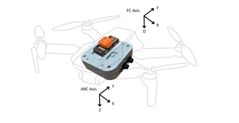
Figure 10: ARC Primary UAV mounting onboard drone; installation orientation relative to flight controller
Interfacing to the ARC Primary
ARC supports integration into MAVLink-based flight controllers and has been tested with a variety of flight controllers. The ARC Primary electrical interface is provided by two external ports, one for power and one for data, as shown in Figure 12.
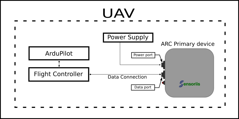
Figure 11: ARC Primary port connections to the UAV
Data Port Connection
The ARC Primary device interfaces with the UAV Flight Controller using MAVLink over a TTL serial UART connection. This connection is provided via the 9-way Data Port connector (see Figure 13 and Table 1). For serial connection electrical specifications, see Specification.
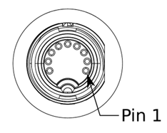
Figure 12: ARC Primary Data Port pin indication
| Pin No | Signal | Description |
|---|---|---|
| 1 | VIN | Positive Power supply input (see Table 4) TODO LINK |
| 2 | UARTA_TX | Config UART TX (Out) |
| 3 | GND | Ground |
| 4 | GND | Ground |
| 5 | UARTA_RX | Config UART RX (In) |
| 6 | Reserved | - |
| 7 | Reserved | - |
| 8 | UARTB_TX | Data UART TX (Out) |
| 9 | UARTB_RX | Data UART RX (In) |
Table 1: ARC Primary Data Port Connector Pinout
For ARC Primary devices, the AC11008 USB Data Cable is provided for bench testing and initial evaluation. This provides a USB bridge interface to the ARC Primary data UART and allows for initial interfacing from a host PC.
Note: The USB host port must be able to meet the input current supply requirements listed in Table 4.
The AC11007 Unterminated Data Cable is also provided to allow direct integration into a host system that can interface with the device UART directly. The pinout for the cable is given in Table 2.
Power Reccomendation
It is recommended to power the ARC primary via the 2-pin Power port for in-system use.
Wire Colour Signal
| Wire Colour | Signal |
|---|---|
| Brown | VIN |
| White | GND |
| Green | Data UART TX (Out) |
| Yellow | Data UART RX (In) |
| Table 2: Signal allocation for AC11007 Data Cable |
Power Port Connection
The ARC Primary device is powered from the 2-Way Power Port connector (see Figure 14 and Table 3). The input voltage and power specifications for the Power Port are given in Table 4.
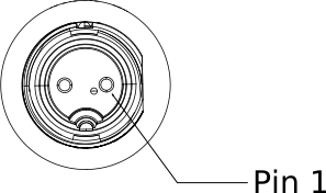
Figure 13: ARC Power Port pinout
| Pin No | Signal | Description |
|---|---|---|
| 1 | VIN | Positive Power supply input (see Table 4) TODO LINK |
| 2 | GND | Power supply ground |
| Table 3: Power Port connector pinout |
| Specificication | Min | Nom | Max | Unit |
|---|---|---|---|---|
| Input Voltage | 5 | 12 | 25 | V |
| Input Power | - | 3.25 | 5 | W |
| Table 4: ARC device power supply requirements |
Overvoltage
ARC will automatically detect over-voltage and power itself down in order to protect the circuitry.